The ESP-01 is a small, cheap ESP8266 based module with WiFi support. It can be put into a deep sleep state where its power consumption is measured in micro-amps. However to wake up after a set amount of time it requires a hardware modification. This article will explain how to enable deep sleep.
The modification connects pin 8 (XPD_DCDC) on the ESP8266 chip to the module’s reset pin. When the onboard clock decides it is time to wake-up it pulls the XPD_DCDC pin Low briefly which causes the ESP8266 to reset.
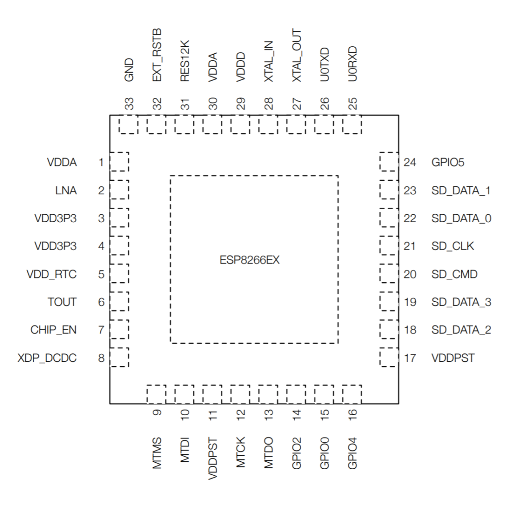
The diagram below shows the location of pin 8 on the module :
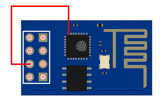
The modification looks a bit scary but becomes easier with practice.
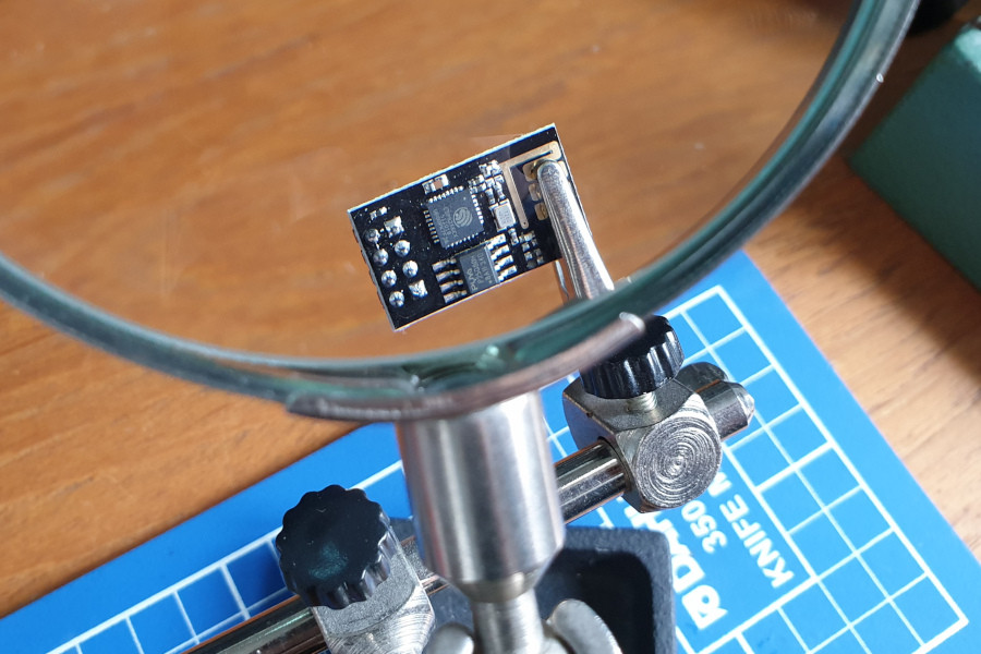
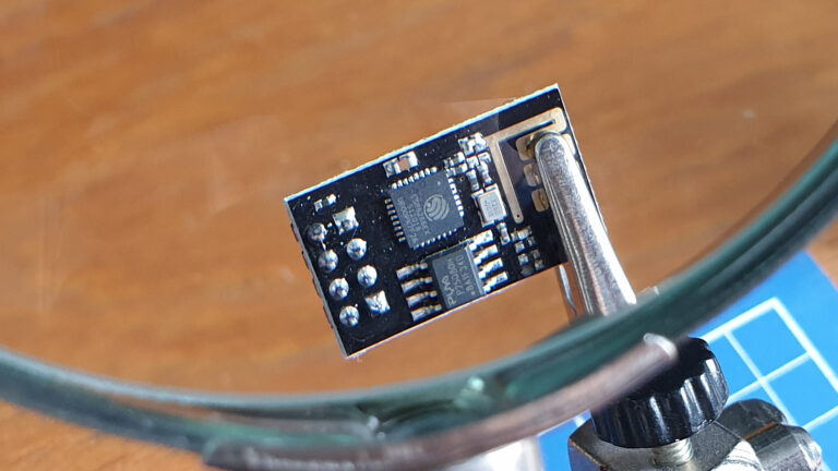
Holding the module in a magnifying glass “helping hand” allows you to see the pin.
I used a strand of thin copper wire and applied a thin layer of solder to one end. I touched the end to the pin on the 8266. Then a few millimetres away from the pin I touched the wire with the soldering iron.
This is enough to melt the solder which then sticks it to the pin. You don’t need to attempt to solder directly to the pin. Heat the wire not the pin!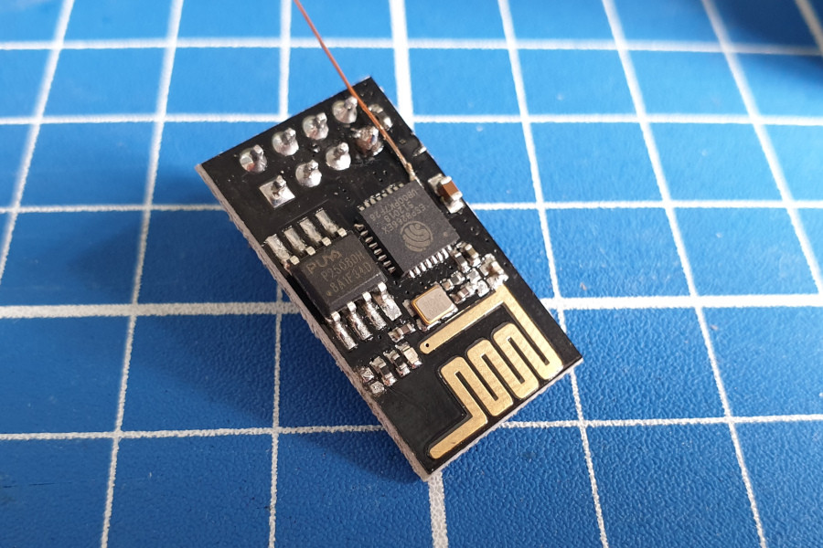
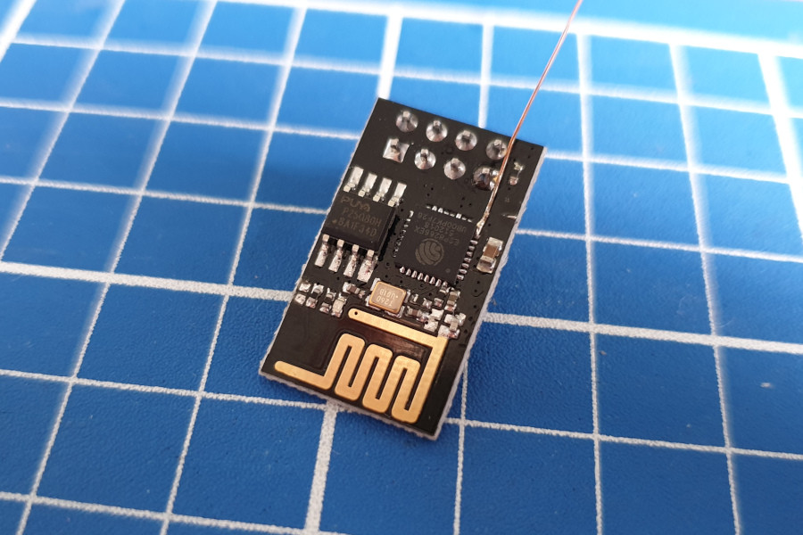
It’s easier than it looks. The connection will be fragile so you may want to secure the wire with a blob of hot glue.
At this point some people then solder the wire to the reset Pin, being careful not to touch any other metal parts.
2-pin Jumper (Optional)
In order to allow me to disconnect this mod I routed the connection via a 2-pin header which I super-glued to the rear of the module.
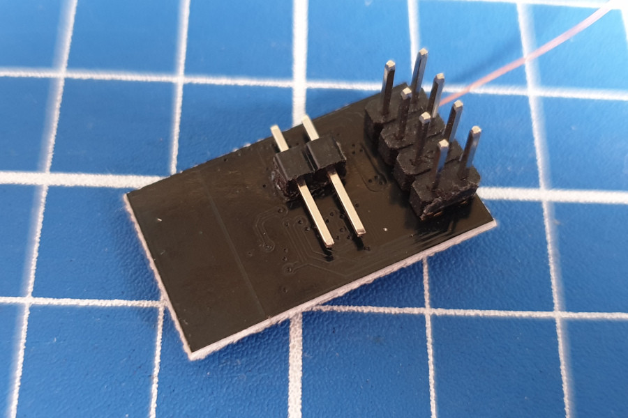
The thin copper wire is soldered to one pin :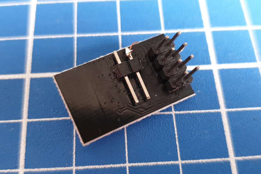
An additional piece of wire is soldered to the other pin :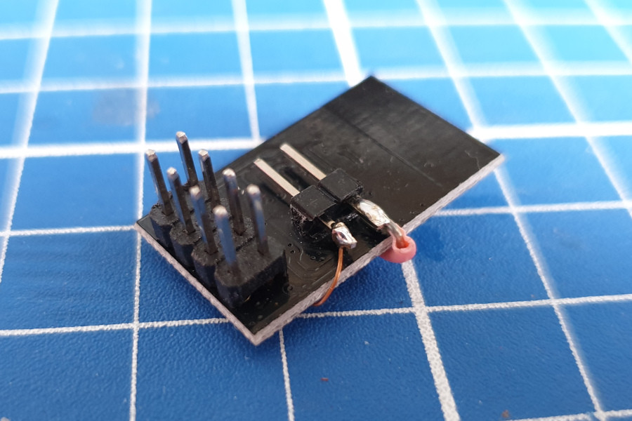
The other end of this wire is soldered to the reset pin. Being normal insulated wire it’s easier to avoid touching other pins :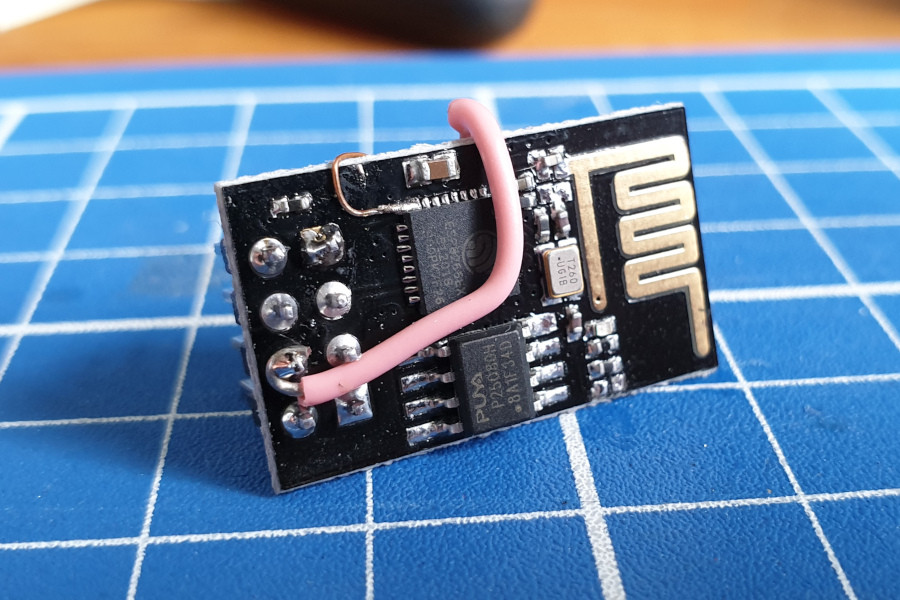
A jumper (shunt) completes the circuit and can be removed if necessary. 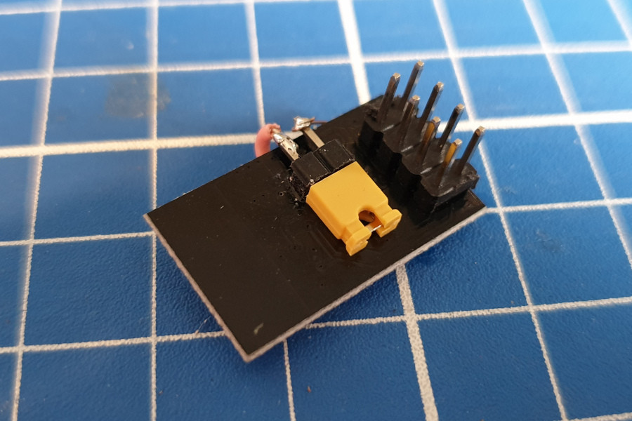
Useful Videos
There are a number of videos on YouTube that show other people performing this mod. Everyone has their own style and technique but I found watching a few of these useful before trying it myself.
This video shows the soldering process although I didn’t use any flux :
This video is a photo slide show but gives a few useful tips :
ESP-01 Deep Sleep Software
Once your hardware is ready you can use deep sleep by adding a single line of code at the end of your Arduino IDE Sketch :
ESP.deepSleep(60 * 1000000);
In this example the module will sleep for 60 seconds (60 million microseconds). If you want to specify the sleep time in seconds you can use a variable and do this :
ESP.deepSleep(sleepSecs * 1000000);
The maximum value you can pass to the deepSleep function is 4294967295. This equates to just over 71 minutes.
If you call deepSleep with a zero like this :
ESP.deepSleep(0);
The module will remain in deep sleep until it sees a rising edge (Low to High) on the reset pin. But if you are doing that you don’t need to worry about this hardware mod.
If you are sceptical about how successful you might be I would recommend practising on a scrap PCB. I was initially worried but decided that the modules are so cheap I could take the risk. Thankfully I’ve modded ten modules and not broken any yet.
There are two things to avoid :
- Don’t get excess solder on the pin next to pin 8.
- Once attached be careful not to tug on the wire as you may rip pin 16 off the PCB
But fortune favours the brave. I believe in you!

8 Comments
Hello Matt,
I have done soldering. It looks functional. ESP-01 is working. But when I put my ESP to deepSleep it won’t wake up. Instead of this I get some unreadable characters and it’s done. Don’t you know what can be a problem ?
Michal
HI Michal i have the same problem here i hope u fine the cuse if u did ihope u can share with me all best kimo
That’s exactly the behavior you see when you haven’t done this mod.
Make sure the wire’s properly connected.
The pin numbering on these chips/boards is confusing enough as it is without being careless. That’s pin 8 if you’re talking about the chip itself (see data sheet). If you’re referring to it as a GPIO pin then it’s GPIO 16.
I’ve corrected the reference to Pin 8. Thanks for pointing it out 🙂
Thanks for the tutorial. I gave it a try and it worked for a while (about an hour 😉 and then it just stopped. Plugging it directly into my system (USB programmer module) it just printed jibberish (rx/tx noise) on the serial console. I took the wire off and its fine but no deep sleep ;-( I’m not sure my soldering skills area good match for this, I’ll just go back to practicing tying my shoes while holding a pumpkin in each hand. Looks like I need to move back to one of the other ESP8266 variants for deepsleep ..
It is beyond any rational reasoning that this chip which is small, low-power, designed to work with a battery wouldn’t have some mechanism for enabling this on the PCB, it just doesn’t make any sense …
Thanks again
Does anyone have the power to update the schematics for this product an place pads for a resistor / jumper ?
I connected the jumper alright, the ESP8266-01 goes with a test of DeepSleepTime 60 into the deepSleep mode, wakes up, but than does it never again. Except I change the time, than again it does it once and that’s it. Any ideas???