ESP-01 modules can be used to create cheap temperature sensors for your home automation system. With a simple hardware mod they can run for months on battery power. This post will describe the battery powered temperature sensor I built to connect to my Raspberry Pi based “Home Assistant” system.
Home Assistant
Home Assistant is an open source home automation system that runs on a Raspberry Pi or a local server. It supports lots of “smart” eco-systems such as Hive, Nest, Philips Hue, IKEA Tradfri etc. It provides a nice “dashboard” interface and can represent sensors and switches. If you can create custom hardware that can send MQTT messages you can interface them to Home Assistant.
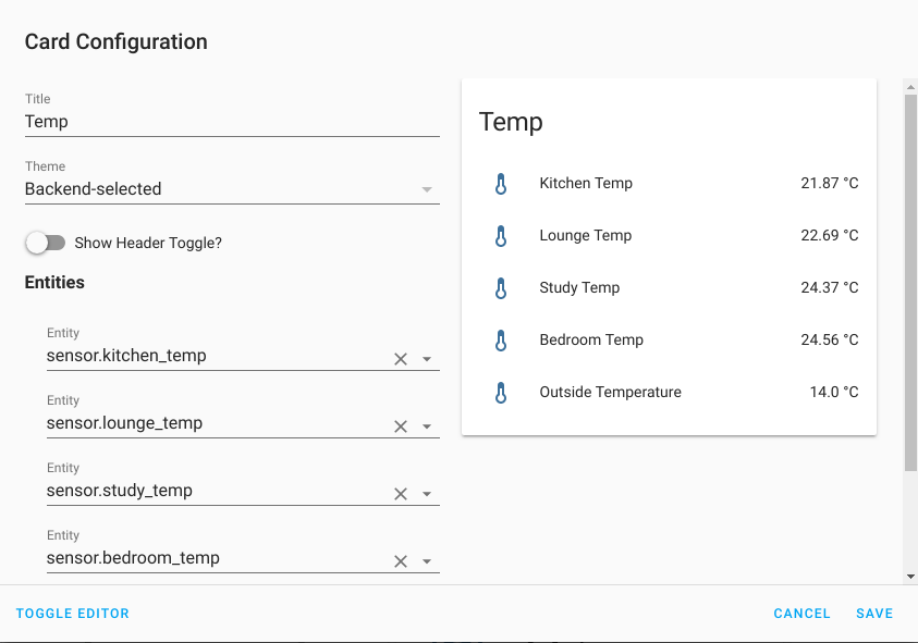
Here is what my ESP-01 Temperature Sensors look like within the dashboard :
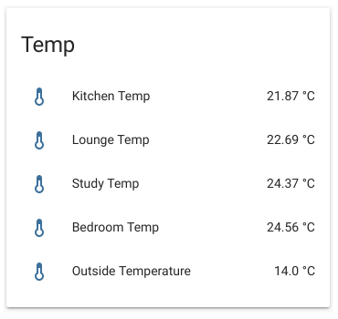
ESP-01 Temperature Sensor
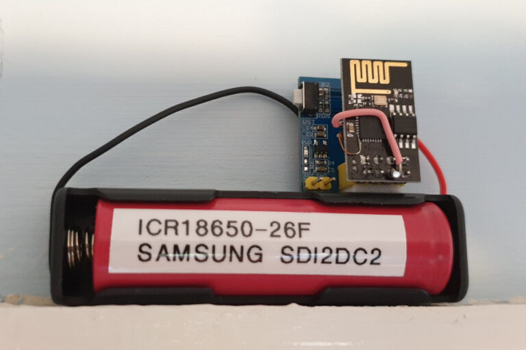
The sensor consists of an ESP-01 module, DS18B20 sensor module and battery. The device reads the temperature and sends an update to Home Assistant via an MQTT message. It then goes into deep sleep for 10 minutes. Then it wakes up and repeats the process. The deep sleep it critical to allowing the sensor to last for months on battery power.
Here is a complete list of parts :
- ESP-01 module (with deep-sleep hardware mod)
- DS18B20 temperature sensor module
- Battery holder
- 18650 battery
ESP-01 Module
The ESP8266 chip is an incredibly popular device and is used on many different home automation devices. The ESP-01 module is one of the smallest and cheapest. It can run Arduino style code and has an integrated WiFi antenna. It has limited input/output capabilities but is perfect for reading one sensor.
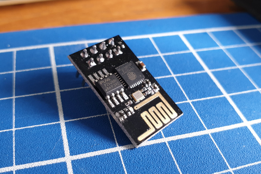
In order to allow the ESP-01 to wake up from deep sleep it needs a hardware modification. This connects one of the pins on the ESP8266 chip to the modules reset pin.
Full details are available on the Enable Deep Sleep on an ESP-01 Module page.
DS18B20 Module for ESP-01
Rather than wire up my own temperature sensor I used a pre-made module designed for use with the ESP-01. The module includes a voltage regulator and a 2-pin header to attach a power source. The exact specification of the regulator is unknown but some sellers list it as supporting 3.7V – 12V inputs.
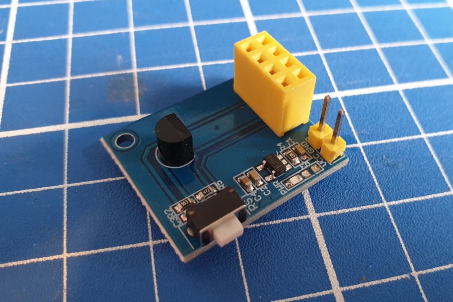
LED Removal
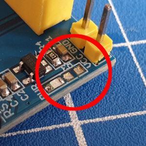
The ESP-01 and DS18B20 modules both have power LEDs on them. Although small they permanently use additional power so I removed both of them. This can be done by heating the LED with a soldering iron and gently removing when the solder melts. I left the blue LED on the ESP-01 as this is only briefly illuminated when the WiFi is active.
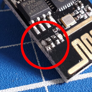
On the DS18B20 I decided to remove the resistor next to LED rather than remove the LED itself. The photo below shows the two pads where the resistor was removed :
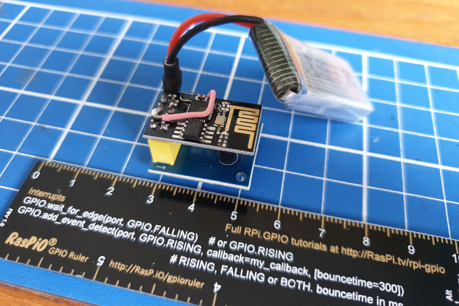
First Prototype Sensor (380mAh LiPo)
My first prototype used a 3.7V 380mAh LiPo.
Second Prototype Sensor (2600mAh LiPo)
For the sensors I wanted to place around the house I decided to use 3.7V 18650 cells. These are now commonly used in Vaping devices (and Tesla cars) but have been traditionally found in power banks and laptop batteries. I had a power bank with a broken connector so opened it up and found four Samsung 18650 cells.
Here is one of my temperature sensors using one of these Samsung cells :
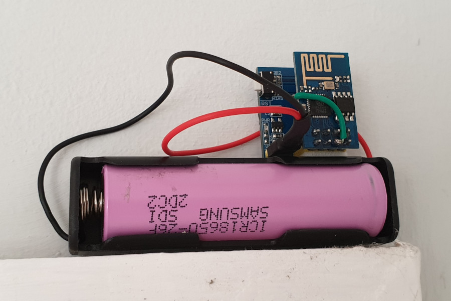
The power bank was an established brand and hadn’t seen much use so I trusted that these cells would be perfectly usable in my sensors.
Charging
Most of my rechargeable batteries are AA or AAA and I had no way of charging 18650 cells. Based on a quick bit of research I bought a Nitecore D4 battery charger.
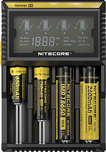
This charges up to four 18650, AA and AAA cells. Unlike my other chargers it can charge individual cells and doesn’t require them to be charged in pairs.
ESP-01 Programming
Programming the ESP-01 is outside the scope of this article but there are plenty of tutorials out there on how to setup the Arduino IDE and programme an ESP-01 using a USB-serial device. I used a CH340 based USB-serial device as it works on both my Windows 10 PC and Ubuntu laptop. I compared a few of these programmers in my ESP-01 Programmers Compared post.
My sketch is available from :
https://bitbucket.org/MattHawkinsUK/home-automation/src/master/esp_01_ds18b20_mqtt/
It consists of three files. These should be placed in a folder named “esp_01_ds18b20_mqtt” before opening in the Arduino IDE.
The “secrets.h.default” file must be renamed to “secrets.h” and will require you to update the values for :
- WIFI_SSID
- WIFI_PASSWD
- MQTT_SERVER
- MQTT_USER
- MQTT_PASSWD
The sketch makes use of 3 libraries which must be added to the Arduino IDE.
- PubSubClient by Nick O’Leary
- OneWire by Paul Stoffregen
- DallasTemperature by Miles Burton
This can be done by using :
Sketch > Include Library > Manage Libraries
then searching for the library name as listed above. If you get a few search results pick the one that matches the correct author.
For information on installing libraries please refer to this page: https://www.arduino.cc/en/Guide/Libraries
You must also add a custom board URL in order to import the required resources to program the ESP8266. This can be done using :
File > Preferences > Additional Boards Manager URLs
and then pasting in the the following URL:
https://arduino.esp8266.com/stable/package_esp8266com_index.json
Finally I set the following options under Tools > Board >
- ‘Generic ESP8266 Module’
- Flash Mode: -> ‘DIO’
- Flash Frequency: -> ’40MHz’
- CPU Frequency: -> ’80 MHz’
- Flash Size: -> ‘512K (FS:64K OTA:~214KB)’
- Debug Port: -> ‘Disabled’
- Debug Level: -> ‘None’
- Reset Method: -> ‘no dtr (aka ck)’
- Upload Speed: -> ‘115200’
When programming the device using the Arduino IDE enable the Serial Monitor (Tools > Serial Monitor) as this allows you to see the Chip ID which you’ll need for the Home Assistant configuration.
Expected Runtime
To estimate the total run-time I ran some tests using some prototypes :
| Prototype 1 | No LEDs removed | 5 min intervals | 380mAh | 10 days |
| Prototype 2 | Blue LED only | 5 min intervals | 380mAh | 17 days |
| Prototype 3 | No LEDs removed | 10 min intervals | 4xAA | 65 days |
| Prototype 4 | Blue LED only | 10 min intervals | 2600mAh | 230 days (estimated) |
Given that most power is used while sending an update it’s the update interval that determines the run-time. If prototype 2 lasted for 408 hours with a smaller battery I would expect Prototype 4 to last 408x2x(2600/380) hours. i.e. 5580 hours or 230 days. I can’t confirm how accurate this is until Prototype 4 stops running in 6 months time.
Home Assistant Integration
Enable MQTT
Assuming you’ve got a working Home Assistant system running the first thing you must do is enable MQTT. This can be done by adding the following block to your “configuration.yaml” file within Home Assistant :
mqtt:
  password: my_mqtt_password
Choose a sensible password. It is important that the ESP-01 sketch is modified to use the correct MQTT password. But once this is done you can upload the same code to every device. It uses the ESP8266 chip ID to publish its data to a unique MQTT topic.
Information on updating the “configuration.yaml” file can be found on the official Home Assistant site.
Add Sensors to HA
The temperature sensors can be configured in the “configuration.yaml” file. I use the “Configurator” add-on in Home Assistant to edit the file in a browser.
The sensors are defined using :
sensor:
  - platform: mqtt
    name: "Lounge Temp"
    state_topic: "house/temp/ESP3831222"
    device_class: "temperature"
    unit_of_measurement: "°C"
  - platform: mqtt
    name: "Kitchen Temp"
    state_topic: "house/temp/ESP3741344"
    device_class: "temperature"
    unit_of_measurement: "°C"
The topic”house/temp/ESP#######” shown above includes the chip ID from the ESP-01. This is outputted to the Serial Monitor when the device is programmed.
Once the configuration has been completed and Home Assistant restarted a panel can be added to the interface :
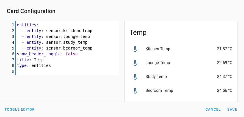
Using “Toggle Editor” sometimes makes it easier to bulk add sensors :
Shopping List
Here are some links to the items I used to create my ESP-01 Temperature Sensor. Other suppliers sell these items but be careful where you get the batteries from. You need to be sure they are good quality, branded and genuine cells.
- ESP-01 module
- DS18B20 temperature sensor module
- Battery holder
- 18650 battery
- Nitecore D4

8 Comments
Excellent write up. Exactly what i was looking for to build my poolthermometer. I use 2x 2500mAh 18650 cells and a MCP1700.
Hi. I’ve just bought some of the boards having hand crafted the waterproof Dallas sensors for my pool.
Since the Dallas is underneath the esp01 it’s difficult to get an external temp. Have you tried unsoldering the Dallas to put it on the underside?
Have you perhaps experienced problems with powering the ESP directly from a LiPo Cell, which could be up to 4.2V when fully charged?
The DS18B20 module has a 3.3V regulator on it. So it can take the full range of voltages and the ESP-01 is fine.
Can the esp01 also output the temperature to a digital display?
The short answer is probably yes. But I would use an I2C screen and temp sensor as then they could use the same two pins.
Hi is it possible to use this with a DHT11 instead so you can get Temperature and Humidity?
I am currently working on this project but I don’t want mine to wake at all only by a reed switch when a window is open and closed how would I do this?